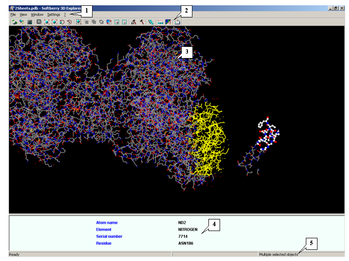
1. Main menu.
2. Toolbar.
3. View area.
4. Information panel.
5. Status bar.
3D Explorer is designed to visualize spatial models of biological macromolecules and their complexes
(below referred to as models). The 3D Explorer application is compatible with PDB files [1].
3D Explorer has an interface compatible with the GetAtoms and CE applications [2,
3].
The macromolecule can be presented as wire, stick, ball and stick, and CPK models.
You can drag a macromolecule model with your mouse, rotate it, and change the size of models.
You can also change the detail level and color of models and their elements.
In 3D Explorer, you can work with several types of molecular elements and show the structural
features of a molecule as a matrix diagram.
|
1. Main menu.
2. Toolbar.
3. View area.
4. Information panel.
5. Status bar.
|
The View menu has the commands for customizing the model view:
Functions of Toolbar buttons:
| Display options - Open the Display options dialog to customize the geometry and color settings for the model. Does the same as: View>Display in the Main Menu. | |
| Light options - Open the Light options dialog to customize settings for lighting the model. Does the same as: View>Light options in the Main Menu. | |
| Color options - Open the Color dialog to select colors for specific chemical elements. Does the same as: View>Colors in the Main Menu. | |
| Full screen - Display the view area in full-screen mode. Does the same as: View>Fullscreen in the Main Menu. | |
| Reset model position - Resets the initial model position. | |
| Fit to window - Change the model size to fit the view area. | |
| Select rotation center mode - When this mode is enabled, the user can assign an atom to be the rotation center for the entire model. | |
| Reset rotation center - Reset the rotation center at the geometrical center of the model. | |
| To turn on the �transformation� mode. In this mode, the movement, rotation and changing of a distance operations can be performed for selected elements of scene only. | |
| Select mode on/off - Enable/disable selection mode. | |
| Normal selection mode - In normal selection mode, each subsequent selection unselects the previously selected item. | |
| OR selection mode - In OR selection mode, all subsequent selections are added to the previously selected items. | |
| XOR selection mode - In XOR selection mode, a previously selected item is unselected by subsequent selection. | |
| Inverse selection - Invert a selection. | |
| Select all - Select all elements of the model. | |
| Unselect all - Unselect all elements of the model. | |
| Model options - Open the Model Options dialog to select the types of atoms, chains, aminoacid residues, and chemical elements to be displayed by the program. Does the same as: View>Model options in the Main Menu. | |
| Options - Open the Options dialog to customize the general view of the model and mouse settings. Does the same as: View>Options in the Main Menu. | |
| Tree model dialog - Open the Tree explorer dialog to view the hierarchical structure of the model elements. Does the same as: Window>Tree dialog in the Main Menu. | |
| Sequence viewer - Open the Sequence viewer dialog to display sequences of protein chains. Does the same as: Window>Sequenc in the Main Menu. | |
| Matrix viewer - Open the Matrix diagram dialog to display specific features of the molecular structure as a matrix diagram. Does the same as: Window>Matrix dialog in the Main Menu. | |
| Help - Refer to Help Topics. Does the same as: ?>Help in the Main Menu. |
Note. Place your mouse pointer over a toolbar button to see the function of this button in the status bar.
The view area displays models in the user-defined view mode. In the view area, you can change the
distance to the model, move and rotate models, and select fragments of the model. Dashed lines indicate hydrogen bonds.
Use the Options dialog to change the background color of the view area.
You can move the border between the view area and the information panel by dragging it with your mouse.
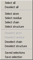
To open a shortcut menu, right-click the view area.
View area shortcut menu |
 |
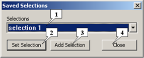 |
1. The list of saved selections.
2. Button for changing of the current scene�s selection to a chosen one.
3. Button for adding of the chosen selection to the already present in the scene ones.
4. Button for closing of the dialog.
|
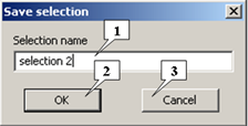 |
1. The selection�s name entry field.
2. Button for saving of the selection and closing of the dialog.
3. Button for canceling of the selection�s saving and closing of the dialog.
|
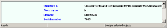 |
The information panel displays:
The status bar displays:
To load a model, click File>Open. In the dialog that appears on your screen, select the file to be loaded. All previously loaded models are deleted from the scene.
To add a model to the existing ones, click File>Add. In the dialog that appears on your screen, select the file to be added.
To change the image quality, do one of the following:
To open the Display options dialog, click:
The Display options dialog has two tabs: Geometry and Sizes. If any of the scene elements are selected, changes will be applied only to the selected elements. If no elements are selected, changes will be applied to all the scene elements.
The Geometry tab is used to specify the types of geometry for the elements of the model.
The The Display options dialog. The Geometry tab |
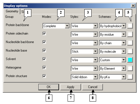 |
1. Group names.
2. Viewing modes.
3. Drop-and-down lists for selecting viewing styles.
4. Drop-and-down lists for selecting color schemes.
5. Buttons for selecting colors in Custom mode.
6. The OK button applies changes and closes the dialog.
7. The Apply button applies changes and leaves the dialog open.
8. The Cancel button closes the dialog and cancels changes.
|
The Group column contains the names of groups with adjustable viewing parameters:
The viewing parameters for a group can be adjusted by selecting the required values in the following columns:
For the Protein backbone group, the following options are available in the drop-and-down lists of the Modes column:
The Styles column has the following options for the Protein backbone, Protein sidechain, Nucleotide backbone, Nucleotide base, Solvent, and Heterogene groups:
The Styles list for the Protein structure group contains the following options:
The Schemes list contains the following options:
Notes:
For the Protein backbone and Protein sidechain groups, the Schemes list contains all available modes.
For the Nucleotide backbone, Nucleotide base, Solvent, and Heterogene groups, the Schemes
list contains only the By Element, By Residue, By Chain,
By molecule, and Custom modes.
For the Protein structure group, the Schemes list contains all modes except for By Element.
On the Sizes tab you can change the geometrical parameters of models.
The Display options dialog. The Sizes tab |
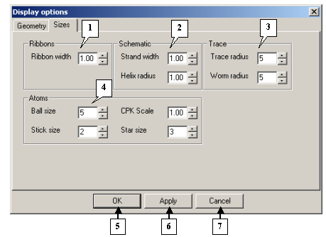 |
1. The Ribbons pane.
2. The Schematic pane.
3. The Trace pane.
4. The Atoms pane.
5. The OK button applies changes and closes the dialog.
6. The Apply button applies changes and leaves the dialog open.
7. The Cancel button closes the dialog and cancels changes.
|
The Light options dialog |
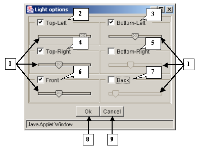 |
1. Sliders.
2. Upper left source.
3. Lower left source.
4. Upper right source.
5. Lower right source.
6. Front source.
7. Background source.
8. The OK button applies changes and closes the dialog.
9. The Cancel button closes the dialog and cancels changes.
|
3D-Explorer allows the user to choose between six light sources that can be selected by checking the corresponding boxes:
Adjust the intensity of the light sources by moving the corresponding sliders.
The Color dialog |
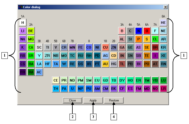 |
1. Buttons for changing the colors of chemical elements.
2. The Close button.
3. The Apply button.
4. The Restore button. |
The Color dialog contains colored buttons that are used to customize the colors of chemical elements. Each color corresponds to a certain element.
Click a colored button with the name of a chemical element to open a dialog for this specific element, for example, "NITROGEN" :
The NITROGEN dialog |
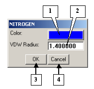 |
1. The button for adjusting the color of the chemical element.
2. The VDW Radius field for changing the default van der Waals radius of the element.
3. The OK button applies changes and closes the dialog.
4. The Cancel button closes the dialog and cancels changes.
|
Color dialog control buttons:
To move the model, drag the molecule image over the view area with your mouse while pressing the
Ctrl key on your keyboard.
If ![]() button
is pressed, only selected elements of the scene can be replaced.
button
is pressed, only selected elements of the scene can be replaced.
You can rotate the model using your mouse. The rotation speed is adjusted in the
Options dialog.
If ![]() button
is pressed, only selected elements of the scene can be rotated.
button
is pressed, only selected elements of the scene can be rotated.
The automatic rotation of the model is disabled by clicking View>Animation>Spin in the main menu. You can customize the rotation speed by setting the rotation delay (in milliseconds) in the Set delay dialog. Select View>Animation>Set delay in the main menu to open this dialog. The automatic rotation of the model is available only in that case when there is no selected elements on the scene.
The Set delay dialog |
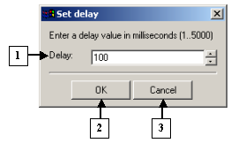 |
1. The field for entering the delay value for shot changes.
2. The OK button applies changes and closes the dialog.
3. The Cancel button closes the dialog and cancels changes.
|
By default, the model turns around its geometrical center. You can change the geometrical center of the model.
To set another geometrical center:
1. Enable the center selection mode by clicking the
![]() toolbar button.
After this, the current geometrical center will be selected.
toolbar button.
After this, the current geometrical center will be selected.
2. Click the atom you want to set as a geometrical center. The new geometrical center will be selected
in the view area.
3. Disable the center selection mode by clicking the
![]() toolbar button.
toolbar button.
You can change the distance to the model using your mouse while pressing the Shift key on your keyboard.
If the mouse pointer is moving downwards, the model is zoomed out; if the mouse pointer is moving upwards, the model is zoomed in.
The scaling speed is adjusted in the Options dialog.
If ![]() button
is pressed, a distance to selected elements of the scene only can be changed.
button
is pressed, a distance to selected elements of the scene only can be changed.
Notes.
To load the initial image of the model, click the
![]() toolbar button.
toolbar button.
To make the model fit the view area, click the
![]() toolbar button.
toolbar button.
You can select specific elements of the model by using your mouse. The selection mode is enabled by clicking the
![]() toolbar button.
toolbar button.
When the ![]() toolbar button
is switched on, the following buttons become available:
toolbar button
is switched on, the following buttons become available:
![]() -
Normal selection mode - In this mode, each subsequent selection unselects the previously selected item.
-
Normal selection mode - In this mode, each subsequent selection unselects the previously selected item.
![]() -
OR selection mode - In this mode, all subsequent selections are added to the previously selected items.
-
OR selection mode - In this mode, all subsequent selections are added to the previously selected items.
![]() -
XOR selection mode - In this mode, a previously selected item is unselected by subsequent selection.
-
XOR selection mode - In this mode, a previously selected item is unselected by subsequent selection.
Click the ![]() toolbar button
to invert a selection.
toolbar button
to invert a selection.
Click the ![]() toolbar button
to select all elements in the model.
toolbar button
to select all elements in the model.
Click the ![]() toolbar button
to unselect all elements of the model.
toolbar button
to unselect all elements of the model.
Note.
The elements of models can also be selected using the Tree explorer
and Sequence viewer dialogs.
You can select specific elements of the model by using Shortcut menu.
To open a shortcut menu, right-click the view area.
View area shortcut menu |
|
|
1. The list of saved selections.
2. Button for changing of the current scene�s selection to a chosen one.
3. Button for adding of the chosen selection to the already present in the scene ones.
4. Button for closing of the dialog.
|
|
1. The selection�s name entry field.
2. Button for saving of the selection and closing of the dialog.
3. Button for canceling of the selection�s saving and closing of the dialog.
|
The Tree explorer dialog contains the hierarchical tree of the elements of a model that can be generated by:
The Tree explorer dialog contains the following elements:
The Tree explorer dialog |
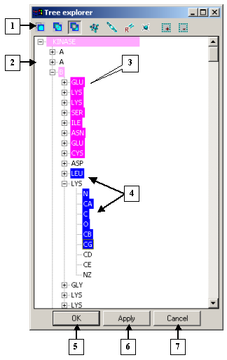 |
1. Control panel.
2. Tree of model elements.
3. Selections applied.
4. New selections.
5. The OK button.
6. The Apply button.
7. The Cancel button. |
![]() - Enable the normal selection mode in which each subsequent selection unselects the previously selected item.
To select an item, click it with your mouse.
- Enable the normal selection mode in which each subsequent selection unselects the previously selected item.
To select an item, click it with your mouse.
![]() - Enable the OR selection mode in which all subsequent selections are added to the previously selected items.
To select an item, click it with your mouse.
- Enable the OR selection mode in which all subsequent selections are added to the previously selected items.
To select an item, click it with your mouse.
![]() - Enable the XOR selection mode in which a previously selected item is unselected by subsequent selection.
To select an item, click it with your mouse.
- Enable the XOR selection mode in which a previously selected item is unselected by subsequent selection.
To select an item, click it with your mouse.
![]() - Expand the tree branch to the molecule level.
- Expand the tree branch to the molecule level.
![]() - Expand the tree branch to the chain level.
- Expand the tree branch to the chain level.
![]() - Expand the tree branch to the residue level.
- Expand the tree branch to the residue level.
![]() - Expand the tree branch to the atom level.
- Expand the tree branch to the atom level.
![]() - Select all elements in the tree.
- Select all elements in the tree.
![]() - Unselect all elements in the tree.
- Unselect all elements in the tree.
The tree shows the hierarchical structure of model elements. You can select elements in the tree with your mouse. Change the selection modes by clicking the control panel buttons.
The selected items are highlighted in blue.
The elements with the applied selection are highlighted in pink.
Dialog control buttons
The Sequence viewer dialog contains:
The Sequence viewer dialog |
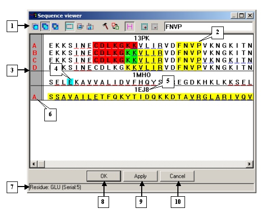 |
1. Control panel.
2. Search result.
3. Sequence view area.
4. Mouse cursor position in the sequence view area (the residue is highlighted in blue).
5. Model name.
6. Chain identifiers.
7. Status bar.
8. The OK button.
9. The Apply button.
10. The Cancel button. |
The control panel buttons have the following functions:
![]() - Normal selection mode. In this mode, each subsequent selection unselects the previously selected item.
To select an item, click it with your mouse or select a rectangular area with your mouse pointer.
- Normal selection mode. In this mode, each subsequent selection unselects the previously selected item.
To select an item, click it with your mouse or select a rectangular area with your mouse pointer.
![]() - OR selection mode. In this mode, all subsequent selections are added to the previously selected items.
To select an item, click it with your mouse or select a rectangular area with your mouse pointer.
- OR selection mode. In this mode, all subsequent selections are added to the previously selected items.
To select an item, click it with your mouse or select a rectangular area with your mouse pointer.
![]() - XOR selection mode. In this mode, a previously selected item is unselected by subsequent selection.
To select an item, click it with your mouse or select a rectangular area with your mouse pointer.
- XOR selection mode. In this mode, a previously selected item is unselected by subsequent selection.
To select an item, click it with your mouse or select a rectangular area with your mouse pointer.
![]() - Rectangle area selection mode. In this mode, the program selects all residues within a
rectangular area defined by the motion of your mouse.
- Rectangle area selection mode. In this mode, the program selects all residues within a
rectangular area defined by the motion of your mouse.
![]() - Lines selection mode. In this mode, the program selects all residues located in the rows
you select by moving your mouse.
- Lines selection mode. In this mode, the program selects all residues located in the rows
you select by moving your mouse.
![]() - Columns selection mode. In this mode, the program selects all residues located in the
columns you select by moving your mouse.
- Columns selection mode. In this mode, the program selects all residues located in the
columns you select by moving your mouse.
![]() - Options. Click this button to open the
Options dialog of the Sequence viewer dialog.
- Options. Click this button to open the
Options dialog of the Sequence viewer dialog.
![]() -
Hide or show elements. Click this button to open the
Visible and hidden elements dialog
in which you can enable/disable some models to be displayed in the sequence view area.
-
Hide or show elements. Click this button to open the
Visible and hidden elements dialog
in which you can enable/disable some models to be displayed in the sequence view area.
![]() - Hide or show headers of elements. In this mode, model names are shown above chain sequences.
- Hide or show headers of elements. In this mode, model names are shown above chain sequences.
![]() - Select all. Select all elements in the list.
- Select all. Select all elements in the list.
![]() - Deselect all. Deselect all elements in the list.
- Deselect all. Deselect all elements in the list.
In the upper right corner of the dialog there is an input field used to search for specified fragments (templates) in chains. Enter a sequence into the field and press Enter. The fragment found will be highlighted in another color.
The sequence view area shows chain sequences in one-letter code. You can select residues within this view area. In the Options dialog, you can change selection modes and color patterns for the sequence view area, including the background color. Note that selection modes can also be customized on the control panel. A residue marked with a red underscore belongs to an a-helix and that with a blue underscore, to a b-structure.
On the left side of the area you can see chain identifiers selected for viewing. The names of chains containing recently selected residues are highlighted (the highlighting color is set in the Options dialog). The background color of chain names is customized in the Options dialog . If you click the chain name, the entire sequence will be selected.
The residues you are pointing to with your mouse is highlighted with a user-defined color.
Dialog control buttons
The status bar shows:
To open the Options dialog, click the
![]() control panel button in the Sequence viewer dialog.
The Options has two tabs: the Common tab which allows you to
adjust selection modes for the Sequence viewer dialog and the Colors
tab which serves to customize the colors of selected residues.
control panel button in the Sequence viewer dialog.
The Options has two tabs: the Common tab which allows you to
adjust selection modes for the Sequence viewer dialog and the Colors
tab which serves to customize the colors of selected residues.
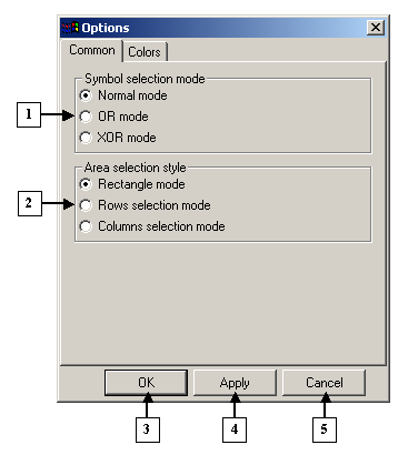 |
1. The Symbol selection mode pane.
2. The Area selection style pane.
3. The OK button.
4. The Apply button.
5. The Cancel button. |
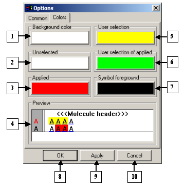 |
1. The Background color pane.
2. The Unselected pane.
3. The Applied pane.
4. The Preview field.
5. The User selection field.
6. The User selection of applied pane.
7. The Symbol foreground pane.
8. The OK button.
9. The Apply button.
10. The Cancel button.
|
Dialog control buttons
To open the Visible and hidden elements dialog, click the
![]() control panel button in the Sequence viewer dialog.
In the Visible and hidden elements dialog, you can change the content and order of models and alignments
as they are displayed in the sequence view area of the Sequence viewer dialog.
control panel button in the Sequence viewer dialog.
In the Visible and hidden elements dialog, you can change the content and order of models and alignments
as they are displayed in the sequence view area of the Sequence viewer dialog.
The Visible and hidden dialog |
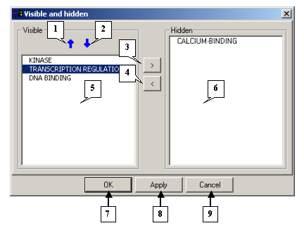 |
1. The button for moving the selected models upwards.
2. The button for moving the selected models downwards.
3. The button for hiding selected models.
4. The button for showing selected models.
5. The Visible list.
6. The Hidden list.
7. The OK button.
8. The Apply button.
9. The Cancel button.
|
To show specific models or alignments, follow these steps:
1. Select the identifiers of models and alignments in the Hidden list by clicking your mouse
(if you want to unselect a selected identifier, click it with your mouse).
2. Click the ![]() button.
After this, the selected identifiers will be removed from the Hidden list and added to the end of
the Visible list in the same order as they were arranged in the Hidden list.
button.
After this, the selected identifiers will be removed from the Hidden list and added to the end of
the Visible list in the same order as they were arranged in the Hidden list.
To hide some models, follow these steps:
1. Select the corresponding model identifiers and alignments in the Visible list by clicking
your mouse (if you want to unselect a selected identifier, click it with your mouse).
2. Click the ![]() button.
After this, the selected identifiers will be removed from the Visible list and added to the end
of the Hidden list in the same order as they were in the Visible list.
button.
After this, the selected identifiers will be removed from the Visible list and added to the end
of the Hidden list in the same order as they were in the Visible list.
To change the order of models in the lists, click the
![]() or
or
![]() buttons to shift a model
one step above or below.
buttons to shift a model
one step above or below.
Dialog control buttons
You can select specific atoms, chains, residues, and chemical elements to be displayed in a model on the Model options dialog. To open this dialog, do the following:
The information pane displays the following data about all loaded models and for the model selected in the drop-and-down list:
1. The total number of chains, residues, and atoms in models and the number of displayed atoms.
2. The number of selected atoms.
Dialog control buttons
You can select a model in the list of model identifiers and change the parameters of the selected model on the Atoms, Residues, Chains, and Elements tabs.
On the Atoms tab, you can select atoms to be displayed in the selected model.
The list contains the names of atoms in a model. To show or hide atoms, check
(![]() ) or uncheck
(
) or uncheck
(![]() ) the corresponding boxes.
Click the control panel buttons to display the following groups of atoms:
) the corresponding boxes.
Click the control panel buttons to display the following groups of atoms:
![]() - all atoms in the list.
- all atoms in the list.
![]() - protein backbone atoms: Ca, N, C, and O.
- protein backbone atoms: Ca, N, C, and O.
![]() - some of the protein backbone atoms: Ca, N, and C.
- some of the protein backbone atoms: Ca, N, and C.
![]() - only Ca- atoms in the protein backbone.
- only Ca- atoms in the protein backbone.
![]() - all hydrogen atoms are hidden.
- all hydrogen atoms are hidden.
The Model options dialog. The Atoms tab |
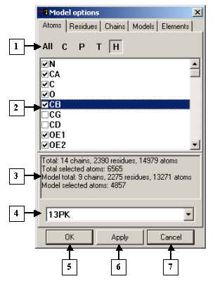 |
1. Control panel.
2. List of atoms.
3. Information panel.
4. List of identifiers of the models loaded.
5. The OK button.
6. The Apply button.
7. The Cancel button.
|
The Residues tab serves to select the residues to be displayed in a model. The list contains chain identifiers with residue ranges for each chain. To change the residue range, select the chain and insert the required values in the from and to fields. If you click the MIN button, the position number of the first residue in the chain appears in the from field. If you click the MAX button, the position number of the last residue in the chain appears in the to field.
The Model options dialog. The Residues tab |
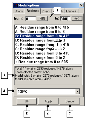 |
1. Fields for changing the range of displayed residues.
2. List of chain identifiers with residue ranges.
3. Information panel.
4. Identifiers of the models loaded.
5. The OK button.
6. The Apply button.
7. The Cancel button.
|
On the Chains tab, you can select the chains to be displayed in a model.
To show or hide chains, check (![]() )
or uncheck (
)
or uncheck (![]() ) the corresponding boxes.
) the corresponding boxes.
The Model options dialog. The Chains tab |
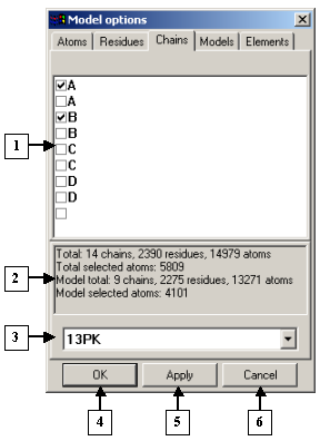 |
1. List of chains.
2. Information panel.
3. List of identifiers of models loaded.
4. The OK button.
5. The Apply button.
6. The Cancel button.
|
The Elements tab serves to select the chemical elements to be displayed in a model.
The list contains the names of chemical elements. To show or hide chemical elements, check
(![]() ) or uncheck
(
) or uncheck
(![]() ) the corresponding boxes.
) the corresponding boxes.
The Model options dialog. The Elements tab |
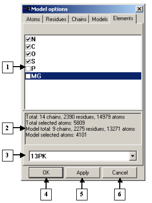 |
1. List of chemical elements.
2. Information panel.
3. List of identifiers of models loaded.
4. The OK button.
5. The Apply button.
6. The Cancel button.
|
The Models tab serves to select the models to be displayed. The list contains model identifiers.
To show or hide models, check (![]() ) or uncheck
(
) or uncheck
(![]() ) the corresponding boxes.
) the corresponding boxes.
The Model options dialog. The Models tab |
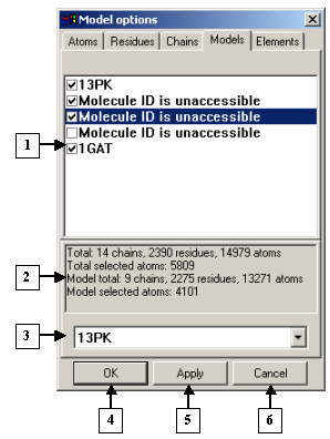 |
1. Model identifiers list.
2. Information panel.
3. List of identifiers of models loaded.
4. The OK button.
5. The Apply button.
6. The Cancel button.
|
On the Options dialog, you can set the general parameters of the model and mouse parameters. To open the Options dialog, do the following:
In the Options dialog, you can change:
The Options dialog. |
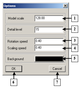 |
1. The field for entering the distance to the model.
2. Detail level.
3. Rotation speed.
4. Scaling speed.
5. The button for selecting the background color for the view area.
6. The OK button.
7. The Cancel button.
|
Dialog control buttons
In the Matrix diagram dialog, you can set the program to display structural features of models as matrix diagrams. To open the Matrix diagram dialog, do the following:
The Matrix diagram dialog. |
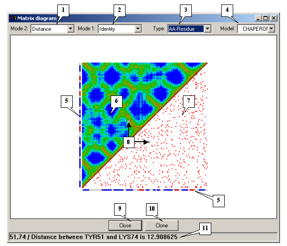 |
1. Drop-and-down list for selecting the mode for the upper matrix.
2. The drop-and-down list for selecting the mode for the lower matrix.
3. Types of elements.
4. Model identifiers.
5. Secondary structure.
6. Upper matrix.
7. Lower matrix.
8. Mouse pointer position.
9. The Close button.
10. The Clone button.
11. Status bar.
|
The color of each cell in the diagram depends in the value of the corresponding matrix element. You can change the type and view mode for your matrices.
Use the Type drop-and-down list to select the types of elements to be displayed in a matrix diagram. The following variants are available:
The upper matrix mode can be selected in the Mode 2 drop-and-down list and the lower matrix mode can be selected in the Mode 1 drop-and-down list. The following matrix modes are available:
In the Model drop-and-down list, select the identifier of the model to be displayed as a matrix. The list contains identifiers of all loaded models.
The secondary molecular structure is shown on the left and below the matrix. a-helix fragments are shown in red, b-structures are blue, and turns and non-structured elements are white.
The status bar displays the following data about the pair of elements marked with the mouse pointer in the matrix diagram: the distance between them in the Distance mode, their resemblance in the Identity mode, the presence or absence of hydrogen bonds in the Hydrogen bonds mode, and the presence or absence of disulphide bonds in the SS bond mode.
Click the Clone button to make a copy of this dialog.
Click the Close button to close this dialog.
 |
1. Basic colors.
2. Custom colors.
3. Slider.
4. Color selector.
5. Current color preview box.
6. The HSB color model.
7. The RGB color model.
8. The OK button.
9. The Cancel button.
10. The Add to Custom Colors button.
|
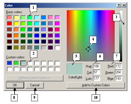
In the Color dialog, you can select colors of your models.
Note. To change a custom color, click the custom color box and then change the color by moving the slider selector or inserting the required values in the HSB or RGB color fields. After this, click the Add to Custom Colors button. The new custom color will appear in the custom color boxes.
Dialog control buttons.
Click the OK button to apply changes and close the dialog.
Click the Cancel button to cancel changes.
1. http://www.wwpdb.org/docs
2. Shindyalov IN, Bourne PE (1998) Protein structure alignment by incremental combinatorial extension (CE) of the optimal path. Protein Engineering 11(9) 739-747.
3. www.softberry.com/berry.phtml?topic=getatoms&group=help&subgroup=propt